Professional equipment settings · photorealistic illustrations
Start with the right code and project
The 2025 California Electrical Code is Title 24, Part 3, based on the 2023 NEC with California amendments. Confirm your project’s governing edition, local amendments, permit date and the authority having jurisdiction (AHJ). A newer national NEC edition does not automatically apply to a California project.
These original summaries cover common installation topics, not every requirement or exception. Hospitals, pools, hazardous locations, solar and batteries need additional specialist review. Electrical work and verification should be performed by qualified professionals with the required permits; this guide does not cover energized work.
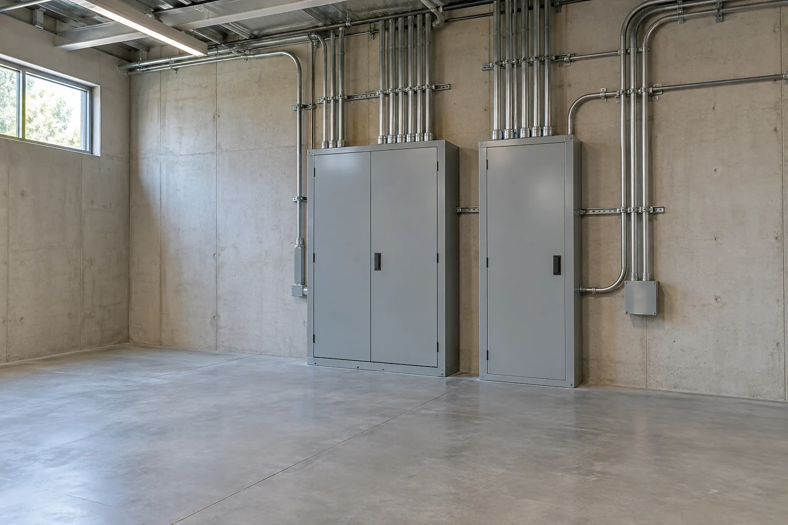
Natural equipment pictures are AI-generated illustrations, not inspected installations. Labeled dimension drawings identify the applicable measurement points and limits; neither picture type is to scale. Read each topic’s scope and exceptions.
Read the labeled arrows from the finished floor to the stated box edge, device center, button top or handle grip. Example heights are design choices; code limits depend on the project. The drawings combine accessories for comparison and do not represent a complete installation plan.
Seven labeled illustrations explain heights above finished floor, outlet spacing and clearances from materials. Code limits and design examples are identified separately. Some accessories have no universal minimum or maximum. Pictures are not to scale.
No matching topics. Try a different word or clear the filters.
Illustrative image · actual dimensions and hidden wiring require verification.Dimension illustration · read the measurement points and scope below.
01Residential
Living-room & bedroom receptacle spacing
CEC 210.52(A)
Place receptacles so everyday equipment can reach power without relying on extension cords.
Read requirements & examples
What to check
For the rooms covered by this section, measure horizontally along the floor line: no point in a qualifying wall space may be more than 6 ft from a receptacle.
On an uninterrupted qualifying wall, this normally permits up to 12 ft between receptacles. Wall spaces 2 ft or wider count; doors, fireplaces and similar breaks affect the layout.
Corners do not automatically restart the measurement. Countertop, hallway and garage requirements are separate. Mounting height also needs review under applicable California accessibility rules.
Quick measurements — verify the stated scope
Maximum distance to a receptacle
6 ft / 1.83 m
Typical maximum separation on continuous wall
12 ft / 3.66 m
Qualifying wall-space width
2 ft / 0.61 m or more
Planning example
A 12 ft uninterrupted wall can be served by a receptacle at its midpoint, provided the entire actual wall space is covered.
Common mistake
Checking only the distance between outlets and overlooking the end of a wall or a short qualifying wall space.
Inspection reminders
Mark doors, fixed features and qualifying wall spaces on the plan.
Check the full floor-line measurement before rough inspection.
Plan both countertop coverage and the required circuits; kitchen protection extends beyond the sink area.
Read requirements & examples
What to check
Wall countertop spaces at least 12 in. wide need receptacle coverage. Along the wall line, keep every point within 24 in. of a serving receptacle.
Provide at least two 20 A small-appliance branch circuits for the required kitchen and related-area receptacles. These are not general lighting circuits; apply the section’s permitted uses and exceptions.
Kitchen receptacles require GFCI protection under the current scope. Check AFCI and tamper-resistant requirements too; GFCI does not replace them.
Quick measurements — verify the stated scope
Countertop width triggering coverage
12 in. / 305 mm
Maximum wall-line distance to serving outlet
24 in. / 610 mm
Maximum ordinary height above countertop
20 in. / 508 mm; see permitted locations
Planning example
For a continuous backsplash, locate serving receptacles no more than 4 ft apart and check both ends and each separated countertop section.
Common mistake
Protecting only the receptacle closest to the sink or using a convenient island outlet to satisfy wall-countertop coverage.
Inspection reminders
Show the two small-appliance circuits on the plan.
Check serving locations, interruptions and protection.
Illustrative image · actual dimensions and hidden wiring require verification.
03Residential
Kitchen islands & peninsulas: the updated approach
CEC 210.52(C)(2)–(3)
The 2023 NEC model changes replaced the old island-area calculation. Do not copy a previous edition’s cabinet-side detail.
Read requirements & examples
What to check
The model rule does not require an island or peninsula receptacle solely because an island exists. If none serves the surface, provide for a future receptacle.
If a serving receptacle is installed, use a location permitted by 210.52(C)(3): on or above the surface within the allowed height, or a listed countertop/work-surface assembly.
A receptacle on the cabinet side below the countertop does not meet the serving-location rule. Confirm local amendments and the inspector’s accepted method of future provision.
Planning example
Plan an approved future pathway and box arrangement with the inspector before cabinets are closed, or specify a listed surface assembly.
Common mistake
Reusing an older drawing with a below-counter cabinet-side receptacle as the required countertop outlet.
Inspection reminders
Record the accepted future-provision detail if no outlet is installed.
Verify the assembly listing and countertop suitability.
Illustrative image · actual dimensions and hidden wiring require verification.Dimension illustration · read the measurement points and scope below.
04Residential
Bathroom receptacles & branch circuits
CEC 210.52(D), 210.11(C)(3), 210.8(A)(1), 406.12
Locate power near each wash basin while keeping it outside prohibited bathtub and shower locations.
Read requirements & examples
What to check
Provide a receptacle within 3 ft of the outside edge of each basin. Review the permitted wall, partition or cabinet placement details.
The tub/shower exclusion extends 3 ft horizontally from outside edges and vertically from floor to 8 ft above the rim/threshold, subject to barriers and specific exceptions in 406.9(C). Bathroom receptacles need GFCI protection and applicable tamper-resistant construction. Receptacle location restrictions near tubs and showers also apply.
Provide at least one 20 A bathroom receptacle circuit. A circuit serving multiple bathrooms cannot also supply their lights; the single-bathroom exception can permit that bathroom’s other loads subject to the code limits.
Quick measurements — verify the stated scope
Basin-edge distance
Within 3 ft / 914 mm
Required receptacle circuit
At least one 20 A circuit
Planning example
For two basins, verify that the actual selected receptacle locations serve both basin edges within the permitted distance.
Common mistake
Putting a receptacle in a prohibited tub/shower zone simply because it is close enough to the basin.
Inspection reminders
Check basin-edge distance and tub/shower restrictions separately. Do not mistake GFCI protection for permission to enter the prohibited zone.
Confirm which bathroom loads the 20 A circuit serves.
Illustrative image · actual dimensions and hidden wiring require verification.
05Residential
Garage & laundry circuit planning
CEC 210.11(C)(2), 210.11(C)(4), 210.52(F)–(G)
Laundry and garage receptacles have their own circuit requirements; a spare living-room circuit is not the starting point.
Read requirements & examples
What to check
Plan the required 20 A laundry receptacle branch circuit separately from general lighting and outlets outside the laundry area.
Attached garages and powered detached garages require at least one 120 V, 20 A branch circuit for their required receptacles. Review permitted outdoor-receptacle exceptions and any additional equipment circuits.
Check garage receptacle locations, GFCI protection and laundry AFCI/GFCI requirements. EV charging and other large loads require a separate load and circuit review.
Planning example
Label the laundry and garage receptacle circuits clearly in the directory and separately evaluate the dryer and EVSE.
Common mistake
Treating an ordinary garage receptacle circuit as available capacity for a high-power charger.
Inspection reminders
Verify required circuits and actual equipment loads.
Test the specified protective devices at final inspection.
Dwelling AFCI requirements cover specified 120 V, single-phase 10 A, 15 A and 20 A circuits serving kitchens, living spaces, bedrooms, closets, hallways, laundry areas and similar spaces.
Use an approved protection arrangement and compatible listed equipment. A combination-type AFCI is not the same description as a dual-function AFCI/GFCI device. Changes to existing circuits need their own review.
Planning example
A circuit may need both AFCI and GFCI protection; choose listed equipment that provides the required functions.
Common mistake
Assuming a receptacle with TEST and RESET buttons automatically provides every required protection.
Inspection reminders
Identify the functions from the actual product markings.
Check accessibility, compatibility and manufacturer test instructions.
Illustrative image · actual dimensions and hidden wiring require verification.
07Residential
Outdoor receptacles & weather protection
CEC 210.8(A), 210.8(F), 406.9, 300.5
Outdoor power needs shock protection, suitable enclosures and wiring rated for the environment.
Read requirements & examples
What to check
Use the required GFCI protection and weather-resistant receptacles. Wet-location covers must provide the specified protection when a cord is connected; choose an extra-duty cover where required.
An underground raceway is a wet location. Select conductors with the complete wet-location rating; putting NM-B in conduit does not make it a wet-location cable.
Burial cover depends on the wiring method, circuit and location; there is no single depth for all work. The printed listed-HVAC exception in the 2023 NEC outdoor-outlet rule expired September 1, 2026; verify current adopted amendments and applicable exceptions before relying on it.
Planning example
Select the enclosure, cover and wet-rated wiring as a system for the actual exposure and cord use.
Common mistake
Using an indoor cover outside or assuming conduit alone makes indoor-only cable suitable underground.
Inspection reminders
Check GFCI, cover listing, weather rating and entry fittings.
Confirm burial method and required cover with the permitting authority.
Illustrative image · actual dimensions and hidden wiring require verification.
08Residential
EV charging & service capacity
CEC Article 220; 625.40–625.42, 625.54
Check building capacity and the charging equipment rating before selecting a circuit.
Read requirements & examples
What to check
EV charging is treated as a continuous load. In an ordinary circuit design, a 40 A charging setting normally requires a circuit rated at least 50 A; wiring and terminals must be selected separately.
Complete the applicable service/feeder load calculation. An empty breaker position does not establish available electrical capacity.
Listed load-management equipment or restricted adjustable settings may change the permitted design when installed under the relevant requirements. Confirm receptacle GFCI rules, manufacturer instructions, permits and utility requirements.
Planning example
Document the commissioned charging setting and any approved load management, rather than relying on the charger’s maximum marketing rating.
Common mistake
Installing a larger breaker because the charger can be turned down later by its user.
Inspection reminders
Provide the load calculation and equipment specification.
Verify circuit design, settings, listing and required inspections.
Illustrative image · actual dimensions and hidden wiring require verification.
09Residential
Residential lighting & California energy rules
CEC Article 410; California Energy Code 150.0(k), 160.5(a)
Electrical safety and energy compliance are separate checks for the same lighting installation.
Read requirements & examples
What to check
Verify luminaire suitability for the environment and for insulation contact where applicable. Follow recessed-light and manufacturer installation requirements.
Under the 2025 Energy Code, review JA8 requirements, wall controls and dimming in habitable rooms, including the listed exceptions.
At least one general lighting luminaire in bathrooms, garages, laundries, utility rooms and walk-in closets needs the applicable automatic-off control. Outdoor lighting and alterations have their own provisions.
Planning example
Specify the light source and its compatible dimmer together, then check the room’s control requirements.
Common mistake
Assuming an LED fixture by itself completes California energy-code compliance.
Inspection reminders
Verify product certification/markings and the applicable exceptions.
Demonstrate controls and retain required compliance documentation.
Illustrative image · actual dimensions and hidden wiring require verification.Dimension illustration · read the measurement points and scope below.
10Residential & commercial
Panel access & working clearances
CEC 110.26(A)–(E)
Reserve access for operation and maintenance, and keep it clear after the building is occupied.
Read requirements & examples
What to check
For the common 0–150 V-to-ground case, required working depth is normally at least 3 ft. Higher voltage-to-ground and opposing surfaces can require more depth; use the applicable table.
Working width is at least 30 in. or the equipment width, whichever is larger. Required height is normally at least 6 ft 6 in. or the equipment height, whichever is larger; review specific exceptions.
The ordinary breaker/switch handle limit is 6 ft 7 in. to the grip center in its highest position; this differs from working-space height. There is no universal minimum panel-bottom height. Doors need the required opening and egress. Dedicated electrical space above equipment is a different requirement from the floor working area; do not route foreign systems through prohibited space.
Quick measurements — verify the stated scope
Common 0–150 V-to-ground depth
3 ft / 914 mm minimum
151–600 V to ground, Conditions 1 / 2 / 3
3 ft / 3½ ft / 4 ft minimum (914 / 1,067 / 1,219 mm); check opposing surfaces and exceptions in Table 110.26(A)(1).
Working width
30 in. / 762 mm or equipment width, whichever is greater
Working height
6 ft 6 in. / 1.98 m or equipment height, whichever is greater
Planning example
For a typical 120/240 V dwelling panel, plan the clear access area using voltage to ground, equipment width and actual obstructions.
Common mistake
Calling 3 ft sufficient for every commercial panel, or using the designated working space for storage.
Inspection reminders
Check voltage to ground, table condition and all dimensions.
Check doors, lighting, egress and dedicated electrical space.
Left: neutral bar on insulating supports. Right: ground bar mounted to metal. Training specimens only.
11Residential & commercial
Grounding, bonding & downstream panels
CEC Article 250, including 250.24, 250.142, 250.148
Bonding connects metal parts into the fault-return path; earth alone is not a substitute for that path.
Read requirements & examples
What to check
Identify the service disconnect and the applicable system bonding point. In an ordinary feeder-supplied downstream panel, keep the neutral isolated from the enclosure and equipment grounding conductors.
Bond the enclosure and required metal components through approved means. Select grounding electrode and equipment grounding conductors using their different code rules.
Separate buildings, existing installations and separately derived transformer systems have additional provisions and exceptions. Verify the actual system before applying a standard downstream-panel detail.
Planning example
Review the neutral isolation and equipment-ground bar arrangement against the panel instructions and feeder design.
Common mistake
Adding a neutral-to-enclosure connection in every panel or assuming a ground rod replaces the equipment grounding path.
Inspection reminders
Identify the actual bonding point and system type.
Verify conductor sizing, continuity and listed bonding means.
Illustrative image · actual dimensions and hidden wiring require verification.
12Residential & commercial
Conductors, breakers & terminal ratings
CEC 110.14(C)–(D), 240.4, 310.15–310.16
Wire size is a design result based on load, wiring method and installation conditions.
Read requirements & examples
What to check
For ordinary copper small-conductor circuits, common overcurrent limits are 15 A for 14 AWG, 20 A for 12 AWG and 30 A for 10 AWG, subject to the applicable exceptions.
Insulation temperature does not override terminal ratings or adjustment factors. NM-B ampacity is limited to the 60°C value even though its conductor insulation is rated 90°C.
Check ambient temperature, grouped current-carrying conductors, continuous loads and voltage drop. Use connectors identified for the conductor material, and achieve the specified termination torque by an approved means.
Planning example
A 90°C conductor rating can help a permitted correction calculation, but it does not automatically allow a higher breaker rating.
Common mistake
Upsizing a breaker to stop tripping without evaluating the circuit and its conductors.
Inspection reminders
Document load, ampacity adjustments and terminal limitations.
Verify breaker compatibility, conductor material and specified torque.
Identify the enclosure, entry fitting and removable cover. Unconnected components shown.
13Residential & commercial
Boxes, splices & accessible covers
CEC 300.15, 314.16, 314.25, 314.29
Give connections a suitable enclosure with enough calculated space and a cover that remains accessible.
Read requirements & examples
What to check
Use an approved enclosure and connectors for the wiring method and environment. A splice hidden behind a finished wall is not made acceptable by wrapping it in tape.
Box fill includes the applicable conductor, device-yoke, internal-clamp, support-fitting and grounding-conductor allowances. Do the calculation; physical fit is not the test.
Secure the cover and preserve access. Larger-conductor pull and junction boxes have additional sizing rules under 314.28. Protect insulation at entries and maintain grounding continuity.
Planning example
Choose a box and listed extension arrangement with documented usable volume before adding a bulky device.
Common mistake
Forcing an added receptacle into an already crowded box or burying a junction-box cover in drywall.
Inspection reminders
Check box fill, fitting compatibility and enclosure rating.
Confirm cover access and equipment-ground continuity.
Illustrative image · actual dimensions and hidden wiring require verification.
14Commercial
Commercial raceways & physical protection
CEC 300.4, 300.11; Articles 342, 344, 358
Select and support the raceway for the actual location, exposure and conductor installation.
Read requirements & examples
What to check
EMT, IMC and RMC have different permitted uses and installation rules. Review corrosion, wet locations, physical damage and the appropriate fitting listings.
Use approved building-supported straps and fittings; follow the specific raceway’s securement spacing and exceptions. A tidy-looking run still needs a support and bonding check.
Check conduit fill and conductor ampacity adjustment separately. Use the site’s conduit-fill tool as a calculation aid and verify the adopted code tables. Provide accessible pulling points and protect penetrations.
Planning example
Specify the raceway, fittings, support system and conductor ratings together for the shop or service area.
Common mistake
Assuming a larger conduit removes the need for conductor ampacity adjustment, or supporting electrical work from an unrelated pipe.
Inspection reminders
Review location suitability, support and bonding continuity.
Check fill, pulling access, conductor ratings and required firestopping.
Illustrative image · actual dimensions and hidden wiring require verification.
15Commercial
Commercial kitchens & GFCI protection
CEC 210.8(B), 210.8(D)
Commercial GFCI rules depend on location, supply characteristics and equipment; they are not limited to ordinary household receptacles.
Read requirements & examples
What to check
The non-dwelling location list includes kitchens, certain food/beverage preparation areas, buffet serving areas and covered sink-adjacent equipment.
For the general non-dwelling receptacle scope, check 125–250 V, single-phase circuits at 150 V or less to ground and 50 A or less, and three-phase circuits at 150 V or less to ground and 100 A or less.
Specific appliance provisions apply separately, including their voltage-to-ground and current limits. Check readily accessible protection, exceptions and manufacturer requirements before selecting the circuit.
Planning example
An office break-room food-preparation area needs a location-based review even when nobody calls it a restaurant kitchen.
Common mistake
Excluding a beverage-preparation area or a covered fixed appliance just because the equipment is commercial.
Inspection reminders
Identify the actual room use and supply characteristics.
Review location and specific-appliance provisions separately.
Illustrative image · actual dimensions and hidden wiring require verification.
16Commercial
Three-phase equipment, motors & disconnects
CEC Articles 430, 440; 110.3(B), 110.22
Match the equipment nameplate and system, then review conductors, protection and disconnecting means as separate items.
Read requirements & examples
What to check
Verify voltage, phase, frequency and the applicable equipment ratings. Do not assume a 240 V motor is interchangeable with a 208 V or 480 V supply.
Motor overload protection and branch-circuit short-circuit/ground-fault protection serve different purposes. HVAC equipment often supplies minimum circuit ampacity and maximum overcurrent-protection markings.
Review the applicable disconnect location, visibility, access, locking provisions and identification. Follow the listed equipment instructions and complete the relevant motor or HVAC calculation.
Planning example
Record the equipment ratings and the disconnect that isolates the actual machine or HVAC unit.
Common mistake
Sizing every motor breaker from a general-purpose wire chart or treating a STOP button as an isolating disconnect.
Inspection reminders
Verify nameplate, supply and approved protection design.
Check disconnect identification, location and required locking provisions.
Illustrative image · actual dimensions and hidden wiring require verification.
17Commercial
Commercial lighting controls & energy compliance
CEC Article 410; California Energy Code 130.1, 130.4
Plan the required controls by space type and document how they will operate.
Read requirements & examples
What to check
Review manual controls, dimming, occupant sensing, daylight response and any demand-responsive provisions for the actual project.
The 2025 rules update manual-control visibility, continuous dimming and occupancy-control timing, with exceptions. Alterations need their own scope review rather than automatic application of every new-building rule.
Specify compatible controls and luminaires, draw the zones and complete required acceptance testing and forms. Energy rules are in Title 24 Part 6, separate from the electrical installation code in Part 3.
Planning example
Show office occupancy-control zones and daylight zones on the lighting plan so the installed controls can be tested.
Common mistake
Installing a sensor without checking its coverage, settings, control zones and required acceptance documentation.
Inspection reminders
Confirm space type, project scope and control sequence.
Complete applicable acceptance tests and documentation.
Illustrative image · actual dimensions and hidden wiring require verification.
18Commercial
Exit signs, emergency lighting & commissioning
CEC Article 700, including 700.3; applicable CBC/CFC provisions
Emergency illumination is a system design and testing task, not just a choice of an EXIT fixture.
Read requirements & examples
What to check
Determine which emergency or standby system classification applies and coordinate required exit signs and egress illumination with the building and fire codes.
Review the power source, circuit arrangement, transfer operation, wiring separation and equipment listing for the actual system. Ordinary room lighting controls must not defeat required emergency operation.
Arrange the commissioning witness test with the authority having jurisdiction and retain the required test and maintenance documentation. The 2023 model code expanded the installation test language to commissioning.
Planning example
Test the complete required emergency operation, including the loss of normal supply, under the approved commissioning plan.
Common mistake
Checking that an exit sign lights normally and treating that as proof the emergency system is ready.
Inspection reminders
Verify approved system design and required egress coverage.
Document commissioning, periodic tests and corrective work.
Dimension illustration · read the measurement points and scope below.
19Residential & commercial
Outlet & switch heights from finished floor
CRC R328.1.2; CBC 11B-308.1.2, 11B-308, 11B-309
Identify the applicable California residential or accessibility rule before setting a mounting height.
Read requirements & examples
Covered newly constructed dwellings
CRC R328.1.2 covers occupant-used receptacles, switches and HVAC controls: at least 15 in. (381 mm) to the box bottom and at most 48 in. (1,219 mm) to its top above the finished floor. Review the section’s exceptions, including dedicated and floor receptacles, appliance/ceiling controls and certain low wall spaces.
Accessible buildings and facilities
Under applicable CBC Chapter 11B provisions, receptacles on circuits of 30 A or less and communication receptacles use box-edge measurements. Unobstructed reach is 15–48 in.; accessible switches and other operable parts must satisfy their reach and operation requirements. Do not apply the unobstructed illustration over a cabinet.
For housing subject to CBC Chapter 11A, separately review 1136A and its exceptions. Chapter 11A and 11B have distinct scopes. An existing-building alteration is not automatically a newly constructed dwelling.
Box-center example
A 4 in. tall box centered at 18 in. has its bottom at 16 in. A box centered at 48 in. has its top at 50 in., exceeding a 48 in. box-top limit.
Common mistake
Calling 12 in. to center a universal California minimum, or measuring from the subfloor instead of the finished floor.
Use the correct reference point for each accessory; some equipment has no universal mounting-height range.
Read requirements & examples
Mounting reference — scope and measurement point matter
Accessory
Height rule or design guidance
Occupant-used switches / HVAC controls
Covered new dwellings: 15 in. min box bottom / 48 in. max box top. Accessible operable parts also need applicable reach review.
Doorbell button
Covered new dwellings: 48 in. maximum to button top from exterior finished floor or landing (R328.1.4).
Breaker / disconnect operating handle
Ordinary CEC limit: 6 ft 7 in. (2.0 m) maximum to grip center in its highest position. Review exceptions and any applicable lower accessibility limit.
Wall lights, sensors, smoke / CO alarms
No single universal floor-height range. Use the product instructions and applicable building/fire/energy rules for the specific device.
Ceiling fan blades
Hunter specifies at least 7 ft above floor; approximately 8–9 ft is performance guidance. Follow the selected fan’s listing and instructions.
Meter equipment, EV chargers, appliance outlets
Coordinate utility standards, product listing, environmental protection, accessible reach where required and approved plans; avoid a generic height.
Switch design example
44 in. to the box top is one possible design choice within the covered residential limits. It is not a statewide required height. Allow for the actual box size and final floor finish.
Protect wiring from nails and screws, and check each material or equipment interface separately.
Read requirements & examples
Wood framing
For bored holes, maintain at least 1¼ in. (32 mm) from the hole edge to the nearest wood edge. Where that distance cannot be maintained, provide required penetration protection covering the vulnerable wiring. Ordinary steel protection is at least 1/16 in. (1.6 mm) thick; listed thinner protection and specific raceway exceptions exist.
For wiring parallel to framing where nails or screws may penetrate, the setback is measured to the wiring’s nearest outside surface under 300.4(D), not the hole center. Structural boring/notching limits must also be checked.
Box face and finished wall
CEC 314.20: in noncombustible finishes, the permitted box setback is generally no more than ¼ in. (6 mm). In combustible finishes, the box must be flush with or project beyond the finished surface. Use suitable listed extensions as needed.
Other accessories and materials
There is no universal minimum gap between neighboring switches, receptacles or boxes. Review listed multi-gang arrangements, box fill, accessibility, finish/fire-rated assemblies and equipment instructions. Luminaires and heaters have product-specific combustible-material and insulation clearances. Panel dedicated space has separate restrictions on foreign piping and systems.
Common mistake
Treating the 1¼ in. framing setback as a required gap between electrical accessories, or applying one heater/light clearance to every product.
California Energy Code lighting provisions are in Part 6. Accessibility, fire protection, green-building requirements and utility service standards may also affect the installation. Local handouts and workplace rules are supplemental references, not replacements for the adopted code.