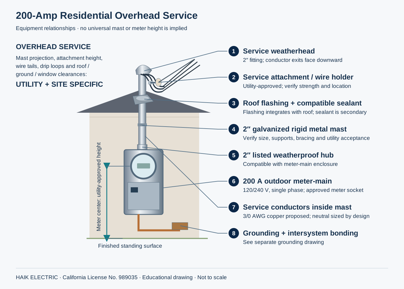
200 A outdoor meter-main
Utility-approved meter socket and outdoor-rated enclosure, typically NEMA 3R. Verify bus rating, main disconnect, available fault current and equipment interrupting / short-circuit ratings.
HAIK ELECTRIC · RESIDENTIAL INSTALLATION GUIDE
Overhead 120/240-volt, single-phase residential service: equipment, heights, clear working space and grounding.
2025 California Electrical Code · 2023 NEC foundation
Effective January 1, 2026 · Reviewed October 12, 2026
SEE HOW THE PARTS FIT TOGETHER
Select a drawing to inspect its labels and measurement points at full size.
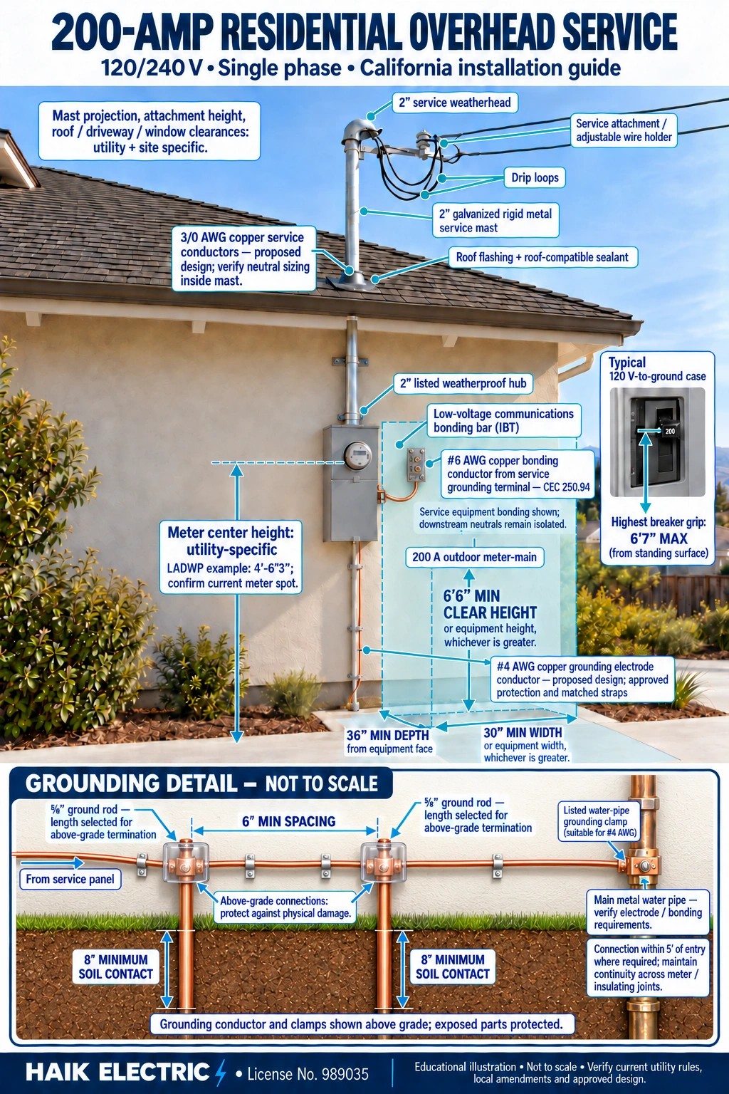
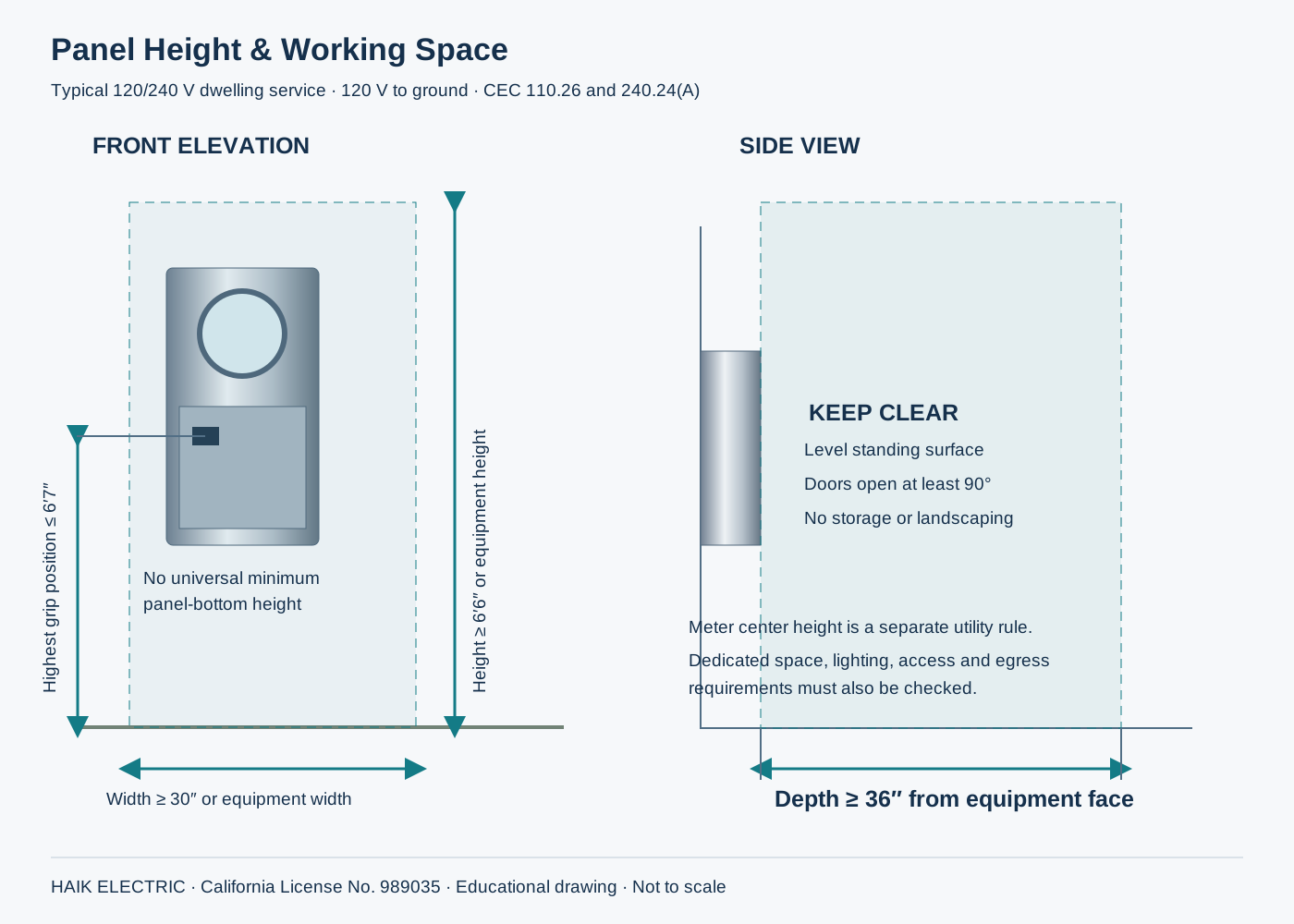
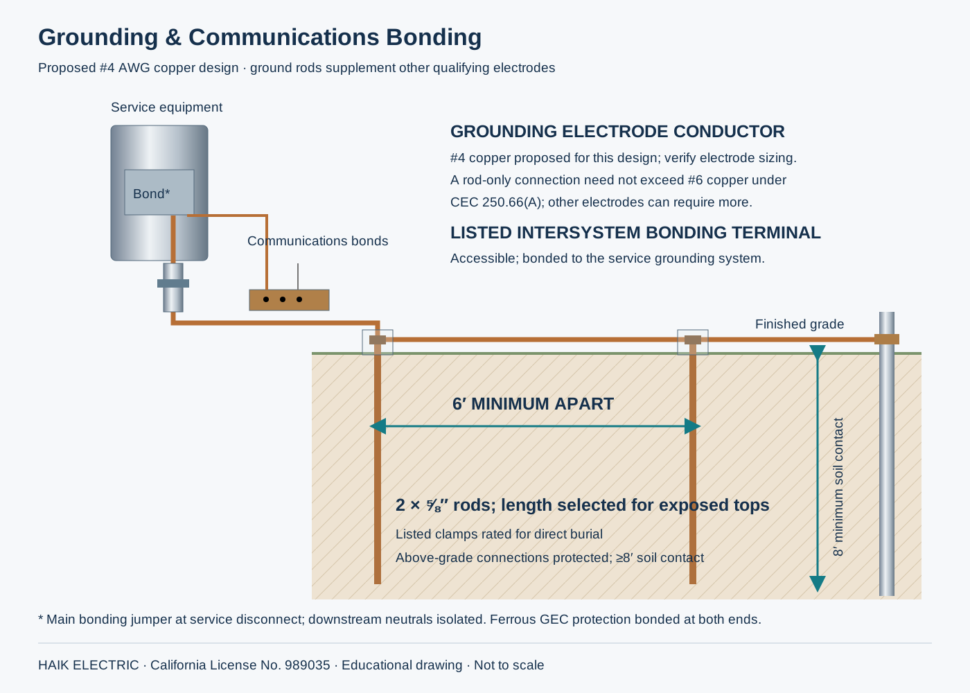
MEASURE FROM THE CORRECT POINT
| Measurement | Requirement / design status | Measurement point |
|---|---|---|
| Working-space depth | 36″ minimum in this typical 120 V-to-ground case | Equipment face to the clear-space boundary |
| Working-space width | 30″ minimum or equipment width, whichever is greater | Clear usable width; panel need not be centered |
| Working-space height | 6′6″ or equipment height, whichever is greater; review applicable exceptions | Standing surface to overhead obstruction |
| Breaker handle | 6′7″ maximum, ordinary accessible installation | Standing surface to grip center in highest position |
| Door opening | At least 90° | Equipment door / hinged panel opening |
| Meter center | Utility-specific; LADWP published example: 4′ to 6′3″ | Finished standing surface to meter-socket centerline |
| Panel bottom | No universal CEC minimum; utility / accessibility / equipment rules can govern | State the required measurement point in the project design |
| Rod spacing | 6′ minimum for multiple rods | Between rods; no universal maximum spacing |
| Rod soil contact | At least 8′ in the normal vertical case | Length in contact with soil, not length above grade |
| Mast projection / bracing | Utility + structural design + equipment requirements | Roof penetration / attachment / mast top as specified |
| Overhead wire clearances | Site-specific; verify CEC 230.24 and 230.9 plus utility rules | Roof, finished grade, driveway, windows, balconies and other surfaces |
| Gas equipment separation | Utility / gas-provider-specific | Check meter, regulator vent and ignition-source rules |
Do not use a single overhead-wire height for every location. Pedestrian areas, vehicle areas, roof slopes and openings have different conditions. Utility meter dimensions can change; confirm the current approved meter spot before construction.
NUMBERED MATERIALS REFERENCE
Utility-approved meter socket and outdoor-rated enclosure, typically NEMA 3R. Verify bus rating, main disconnect, available fault current and equipment interrupting / short-circuit ratings.
Proposed service mast. Verify utility minimum, conductor fill, structural strength, wall supports, roof projection, bracing and attachment loading. Do not substitute EMT for a load-bearing mast.
Listed weatherproof hub approved for the chosen enclosure. Confirm grounding and service-raceway bonding; a fitting must provide the required function, not merely fit the opening.
Listed service-entrance head. Show downward conductor exits and drip loops. Placement relative to the service attachment and required conductor tails follows CEC 230.54 and utility standards.
Utility-approved service attachment and insulator. Attach to suitable structural support or an approved load-bearing mast; verify loading and fasteners.
Flashing / boot compatible with the mast diameter, roof slope and roof material. Integrate with roofing according to manufacturer instructions.
Use roofing cement only when approved for that roofing and flashing. It supplements correctly installed flashing; it is not the primary waterproofing detail.
Proposed ungrounded conductors: 3/0 copper is 200 A at the 75°C table rating before applicable corrections and adjustments. Use wet-location-rated insulation such as THWN-2, compatible terminals and verified load calculations. Neutral size requires a separate calculation. Qualifying whole-dwelling services may use CEC 310.12; 3/0 copper is not a universal residential minimum.
Connect all qualifying electrodes present, including applicable metal underground water piping and concrete-encased electrodes. Evaluate water-pipe and other required bonding. Two rods alone do not describe the complete system.
Show a two-rod design, minimum 6 ft apart, with at least 8 ft in contact with soil for the normal vertical installation. This above-grade connection illustration requires rods long enough to preserve that soil contact; protect rod tops, clamps and exposed conductors against physical damage. The continuous proposed #4 copper conductor runs from service equipment through rod 1 and rod 2 to the qualifying main metal water pipe. The communications bonding bar has its own separate connection from the service grounding terminal. Check rocky-ground exceptions. The second rod is not universally required when an allowed resistance test establishes 25 ohms or less; this guide proposes two rods without relying on that test.
Proposed design specification. Table 250.66 calls for #4 copper with 3/0 copper service conductors where the table applies. Rod-only connections have the 250.66(A) sizing limit; concrete-encased and other electrodes have separate provisions. Specify listed protection rather than generic “BX armor.” Bond ferrous protective raceways / armor as required at both ends.
Suitable for conductor and electrode sizes; direct-burial rated where buried. Maintain required access or use permitted buried electrode connections. Protect exposed components from damage.
Listed strap matched to the selected cable or protective raceway. Support spacing and attachment follow the actual wiring method and product instructions; no universal “BX strap spacing” applies.
Listed accessible terminal for communications bonding, connected separately with the proposed #6 copper conductor from the bonded terminal at service equipment under CEC 250.94. It is not a separate isolated grounding system for low voltage.
A COMPLETE GROUNDING SYSTEM
At the service disconnect: provide the main bonding jumper according to the equipment listing and CEC requirements. Bond service raceways and enclosures. An exterior emergency disconnect is required for applicable one- and two-family dwelling installations under CEC 230.85; identify whether the selected device is service equipment or another permitted emergency-disconnect arrangement.
Downstream panels: keep neutral conductors isolated from equipment grounding conductors and enclosures. The service bonding point and grounding-electrode connection must follow the actual disconnect arrangement.
Armor is not a substitute for the grounding conductor. Use a properly sized copper grounding electrode conductor. If ferrous protection surrounds it, bond that protection as required by CEC 250.64(E). Select straps and fittings for the actual listed product.
Communications bonding: provide an accessible listed intersystem bonding terminal connected to the building service grounding system. Do not create an independent “low-voltage ground rod.”
FROM LOAD CALCULATION TO FINAL INSPECTION
CEC: 110.3(B), 110.14(C), 110.26; 230.9, 230.24, 230.28, 230.54, 230.85; 240.24(A); 250.24, 250.50, 250.52(A)(5), 250.53(A), 250.64, 250.66, 250.92, 250.94; 310.12, Table 310.16 and Chapter 9 conductor-fill tables. Verify adopted text and applicable exceptions.
Utility rules supplement the adopted electrical code. This guide does not establish one statewide meter-height or mast-height standard.